

An efficient strategy to improve photoelectrochemical performance of TiO2 nanowire arrays by optimization electrolytes
doi: 10.19789/j.1004-9398.2026.04.001
-
摘要:
优化电极的光电化学(PEC)性能, 对于以化学能形式有效利用太阳能具有重要意义。本研究旨在通过优Na2SO3和Na2SO4电解质, 提升TiO2纳米线阵列电极的PEC性能。结果表明: TiO2纳米线阵列电极在Na2SO3电解质中的PEC性能显著提高, 光电流密度为0.8 mA/cm2, 是Na2SO4电解质的5倍。在
λ =390 nm处, Na2SO电解质中获得入射光子到电流的转换效率为14.7%, 是Na2SO4电解质中的2.6倍。莫特肖特基和电化学阻抗谱测量实验表明, PEC性能的提高归因于SO32-消耗空穴引起的光生电子和空穴的有效分离。本研究结果为通过选择最佳电解质来提高电极的PEC性能提供了一种有前景的策略。Abstract:Optimization of photoelectrochemical (PEC) performance for electrode is very important to efficiently utilize solar energy in the form of chemical energy. The aim of this study is to optimize the PEC performance of TiO2 nanowire array electrodes via the optimization of Na2SO3 and Na2SO4 electrolytes. The electrode shows significant improvement for the PEC performance in Na2SO3 electrolyte with a photocurrent density of 0.8 mA/cm2, which is 5 times higher than that in Na2SO4 electrolyte. The incident photon-to-current conversion efficiency obtained in Na2SO3 electrolyte is 14.7% at
λ = 390 nm, which is 2.6 times higher than that in Na2SO4 electrolyte. The Mott-Schottky and electrochemical impedance spectroscopy measurements experimentally show that the improved PEC performance is attributed to the efficient separation of photo-generated electrons and holes induced by the consumption of holes by $ \mathrm { S O } _ { 3 } ^ { 2-} $. The results of this study provide a promising strategy to improve the PEC performance of electrode by choosing the optimal electrolyte. -
0. Introduction
Considerable research efforts have recently been motivated to utilize sustainable solar energy to generate clean energy due to the sustained growth in energy demands, gradual decrease of conventional fossil energy and increasingly serious problems for the environment. Therefore, many strategies have been developed and applied to exploit solar energy in subtle ways. Among these strategies, solar-driven photoelectrochemical(PEC)water splitting using metal oxide electrodes has been considered as a promising approach to utilize solar energy in the form of chemical energy and/or electricity[1-3]. Thus, many metal oxides such as TiO2[1, 3-4], WO3[5-7], ZnO[8-9], and BiVO4[10-13] have been extensively received as electrodes for PEC water splitting.
Used as electrodes, TiO2 possesses several advantages, such as high stability, low cost and environmentally benign. In addition, TiO2 has been widely studied as a promising electrode because of its appropriate conduction band(CB)level, which is capable of splitting water to generate H2[14-16]. However, rapid recombination of photo-generated carriers in the TiO2 electrode significantly limits its performance. In order to address this issue, one of the efficient approaches is to fabricate novel complex TiO2-based heterostructure. For example, a 7.8-fold photocurrent improvement was obtained in TiO2/Au/Cu2O nanorod arrays(NRAs)heterostructures compared to pure TiO2 nanorods(NRs)[14]. Co-doping rutile TiO2 NRAs achieved a photocurrent density of 1.45 mA/cm2 at 1.23 V versus reversible hydrogen electrode(RHE)and a hydrogen production rate of 26.17 μmol/cm2/h[17]. Coupling with other semiconductors such as Fe2O3[16], CdSe[18], and CdS[19-20] is another efficient method to improve the performance of TiO2 electrode. As reported in previous literature, the highest photocurrent of approximately 36 mA/cm2 was obtained by Cu2S-TiO2/TiO2 single bond NP/FTO photoanode under 0.5 V potential(E versus RHE, 1 mol/L KOH)[21]. A p-n junction electrode of Cu2O-TiO2 heterojunction nanosheet photoanode achieved a photocurrent density of 0.3 mA/cm2, which was 7.5 times that of TiO2[22]. Cu/CuO-decorated hydrogenated TiO2 nanotubes exhibited enhanced absorption of visible light, leading to a photocurrent of 3.6 mA/cm2 and a photo-conversion efficiency of 2.48% at 1.23 V versus RHE[23]. In addition, non-metals were also applied to dope TiO2 structures to enhance the PEC performance of TiO2 electrode[24-25].
As is well known, the photo-induced electrons and holes should not be recombined at the electrode/electrolyte interface before being used for taking part in PEC reactions, so both the electrode and the electrolyte are crucial for achieving optimal PEC performance. However, so far there have been few studies on the effects of electrolytes on the PEC performance of electrodes[5-7, 26-27]. In the studies on PEC performance of TiO2 electrode, Na2SO4 aqueous solution is one of the most common electrolytes[1, 14, 23, 28-32]. As a scavenger, Na2SO3 can deplete holes to prevent electrons and holes from recombination, resulting in the efficient separation of electron-hole pairs and the improvement of PEC performance. Therefore, Na2SO3 is also widely used as an electrolyte to study the PEC performance of electrodes[33-35].
In this study, we grew TiO2 NWAs on fluorine-doped tin oxide(FTO)glass substrates via a facile hydrothermal process. The effects of Na2SO4 and Na2SO3 electrolytes on the PEC performance of TiO2 nanowire array electrodes were studied. PEC measurements demonstrate that the TiO2 nanowire array electrode shows significantly enhanced performance in Na2SO3 electrolyte. Mott-Schottky(MS)and electrochemical impedance spectroscopy(EIS)measurements clearly show that the enhanced PEC performance of the TiO2 nanowire array electrode in the Na2SO3 electrolyte is ascribed to the efficient separation of electrons and holes, which is induced by the depletion of holes with SO32-.
1. Experimental
1.1 Preparation of TiO2 nanowire arrays(NWAs)
TiO2 NWAs were prepared by a facile hydrothermal method as reported in previous literature[36]. Briefly, a mixed solution containing separate 15 mL ultrapure water and 15 mL HCl(38%)was stirred for 5 min, followed by slowly adding 0.5 mL titanium butoxide under stirring. Afterwards, the formed clear solution with a piece of cleaned FTO substrate against the wall of autoclave was heated in a 50 mL stainless steel autoclave at 150 ℃ for 3.5 h in a box-type electric furnace. Finally, the FTO substrate with grown TiO2 NWAs was washed several times with absolute ethanol and deionized water, then dried and heated at 450 ℃ for 30 min in a tube furnace.
1.2 Characterization
The obtained TiO2 NWAs were characterized by scanning electron microscopy (SEM)for the morphology, size and surface features. The X-ray diffraction(XRD) technique was used to characterize the composition of TiO2 NWAs. UV-vis absorption spectra of TiO2 NWAs were obtained on a Lambda 950 UV/Vis/NIR spectrometer.
1.3 PEC measurements
The PEC measurements were carried out in a typical three-electrode quartz cell configuration with a saturated Ag/AgCl as reference electrode and a Pt wire as counter electrode. The area of working electrode(FTO glass substrate)with TiO2 NWAs was 2.25 cm2, and 0.5 mol/L Na2SO4 and 0.5 mol/L Na2SO3 aqueous solutions were used as the electrolytes, respectively. A 300 W xenon lamp with an AM 1.5G filter was used as the light source. The linear sweep voltammograms(LSVs)were measured with a sweep rate of 5 mV/s and the sweep range from -0.7 to 1.0 V versus Ag/AgCl under illumination. The MS and EIS were measured on a CHI760C electrochemical workstation under dark conditions and 1 sun illumination. The potential range for MS measurements was from -0.8 to 0.4 V versus Ag/AgCl, and the frequency was 1 000 Hz. The EIS was measured at open circuit potential with the frequency of 1 to 10 000 Hz.
2. Results and discussion
2.1 Characterization
Figure 1 shows XRD patterns of TiO2 NWAs and pure FTO glass substrate. All diffraction peaks of the TiO2 NWAs can be indexed to rutile phase TiO2 with a space group of P42/mnm and lattice constants of a=b=4.593 7 and c=2.958 7 Å(JCPDS No.78-2485). It can be seen that the peak intensity corresponding to the (002) crystalline plane at 2θ=62.76° was significantly increased, while the peak intensities corresponding to (111), (211), and (112) crystalline planes were greatly suppressed, and the diffraction peak corresponding to(110)crystalline plane even disappeared. The XRD patterns indicate that the TiO2 NWAs with rutile phase mainly grew along the preferable orientation along [001] direction on the FTO substrate[36-37].
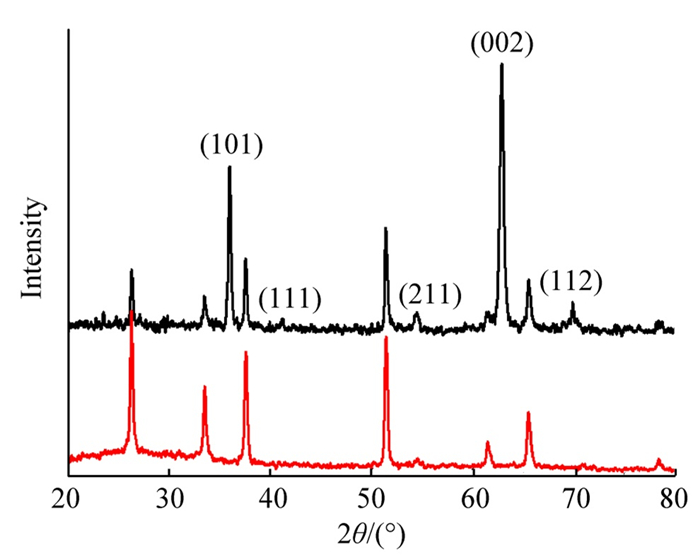 Fig. 1 X-ray diffraction(XRD)patterns of TiO2 nanowire arrays (NWAs)(black line) and the fluorine-doped tin oxide(FTO)substrate(red line)
 下载:
全尺寸图片
The shape and size of the TiO2 NWAs grown on the FTO substrate were measured by SEM as shown in figure 2. The SEM images with different magnifications showed that the highly ordered TiO2 NWs grow on the whole surface of FTO substrate. Moreover, these NWAs were nearly vertical to the FTO substrate. In the higher magnification image, it can be seen that the NWs are composed of nearly quadrangular prisms with an unsmooth square-like top surface. The cross-section diameter of these NWs was almost uniform and is about 250 nm in an average size.
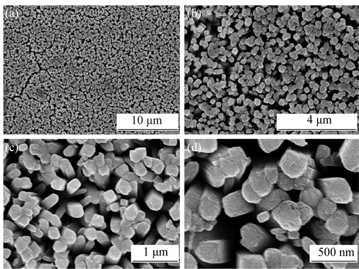 Fig. 2 scanning electron microscopy(SEM)images with different magnification of TiO2 NWAs grown the FTO substrate(a)low; (b, c)medium; (d)high下载:
全尺寸图片
2.2 Optical properties
Figure 3(a)shows the UV-vis diffuse reflectance spectrum(DRS)of the as-achieved well-aligned TiO2 NWAs. In the collection of spectra, BaSO4 was used as the internal reflectance standard. The spectrum shows a high absorbance near the wavelength of 380 nm, but there is almost no absorption at wavelengths longer than 400 nm. This result indicates that the as-prepared well-aligned rutile TiO2 NWAs show a strong absorption in the UV region. The bandgap value of achieved TiO2 NWAs could be determined by combining the Kubelka-Munk function with the Tauc plot[38-39]. The bandgap value of achieved TiO2 NWAs was about 3.0 eV, calculated by the tangent line intercept of (F(R)hν)1/2 versus hν plot as shown in figure 3(b).
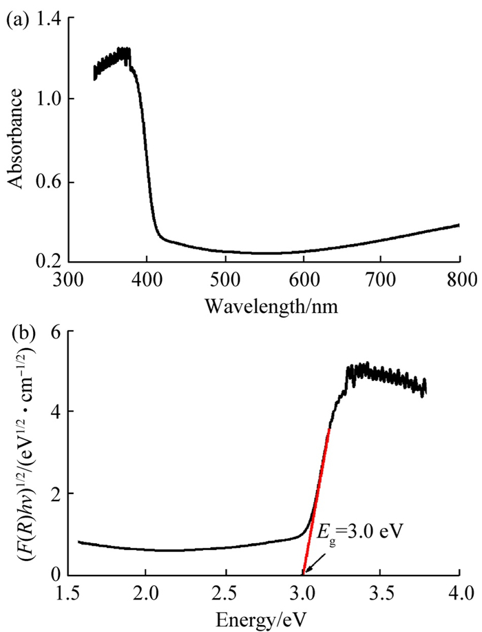 Fig. 3 optical property of TiO2 NWAs(a)UV-vis diffuse reflectance spectrum; (b)(F(R)hν)1/2 versus hν plot of TiO2 NWAs下载:
全尺寸图片
2.3 PEC performance
PEC performance measurements were carried out in Na2SO4 and Na2SO3 electrolytes, respectively. It has been reported that photocurrent density is an indirect representation for the ability of an electrode to generate electrons and holes under light illumination, as well as the photocurrent density is also an indirect representation for the separation efficiency of electrons and holes during the PEC reaction process. In general, a higher electron-hole separation results in a higher photocurrent density[40-41]. Figure 4 shows the chronoamperometric photocurrent density of the TiO2 nanowire array electrode in separate Na2SO4 and Na2SO3 electrolyte solutions under a 300 W xenon lamp illumination with a power intensity of 100 mW/cm2.
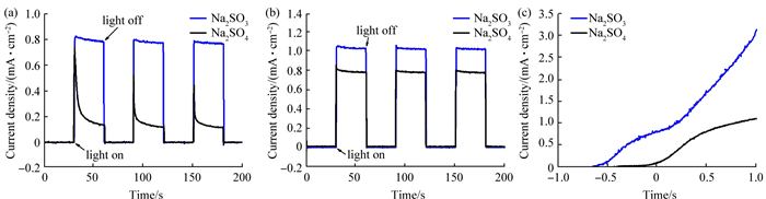 Fig. 4 I-t curves measured in both Na2SO4 and Na2SO3 electrolytes(a)0;(b)0.5 V versus Ag/AgCl; (c)linear sweep voltammograms(LSV)curves下载:
全尺寸图片
Figure 4(a) shows the photocurrent-time(I-t)curves of the TiO2 nanowire array electrodes in Na2SO4 and Na2SO3 electrolytes, respectively. It can be seen that the TiO2 nanowire array electrode shows immediate photoresponse in both Na2SO4 and Na2SO3 electrolytes. However, when the light is turned on, the TiO2 nanowire array electrode shows a spike-like photocurrent in Na2SO4 electrolyte. This spike-like photocurrent is induced by the accumulation of photogenerated holes at the interface of the TiO2 nanowire array electrode and Na2SO4 electrolyte as reported in the previous literature[42]. Whereas the accumulation of holes results from the charge carrier oxidized trap states in TiO2[43] or a slow oxidation reaction of holes at the interface of the TiO2 nanowire array electrodes and Na2SO4 electrolyte[44]. The spike-like photocurrent experimentally shows that photogenerated electrons and holes of TiO2 nanowire array electrode are not separated efficiently during the PEC reaction process in Na2SO4 electrolyte. Such spikes for photocurrents can be effectively suppressed when the holes are used to oxidize the electrolyte. This is true for the Na2SO3 electrolyte, in which the spikes for photocurrents disappeared because the holes are consumed by Na2SO3 electrolyte, a sacrificial agent(SO3 2-)for holes. As a result, the photocurrent density of TiO2 nanowire array electrodes in Na2SO3 electrolyte reaches up to 0.8 mA/cm2, which is 5 times higher than that in Na2SO4 electrolyte at 0 versus Ag/AgCl. Moreover, the TiO2 nanowire array electrode shows a reproducible photocurrent during the on-off cycles in Na2SO3 electrolyte, indicating that most of the photogenerated electrons are used to generate current under light irradiation[45]. Figure 4(b) shows I-t curves of the TiO2 nanowire array electrode in both Na2SO4 and Na2SO3 electrolytes at an applied potential of 0.5 V versus Ag/AgCl. In the first on-off cycle, the electrode also shows spike-like photocurrent in Na2SO4 electrolyte, although applied potential has capability of driving the separation of photoexcited electrons and holes. The results indicate that photoexcited electrons and holes of TiO2 nanowire array electrodes are also not separated efficiently in Na2SO4 electrolyte even at an applied potential. Therefore, the improved photocurrent density of TiO2 nanowire array electrodes in Na2SO3 electrolyte is attributed to the efficient separation of photoexcited electrons and holes, which is induced by the consumption of holes with Na2SO3 electrolyte.
The linear sweep voltammograms(LSVs)were measured in the range of -0.7-1.0 V versus Ag/AgCl electrode. As an n-type semiconductor, the TiO2 nanowire array electrode generates anodic photocurrent as presented in figure 4(c). The onset potential in the Na2SO3 electrolyte is about -0.6 V versus Ag/AgCl electrode, which is much lower than the value(-0.1 V versus Ag/AgCl)in Na2SO4 electrolyte. This result indicates that a lower oxidation potential is needed in the Na2SO3 electrolyte. As a result, the TiO2 nanowire array electrode produces a photocurrent density of over 3 mA/cm2 in Na2SO3 electrolyte, which is 3 times higher than that in Na2SO4 electrolyte at an applied potential of 1.0 V versus Ag/AgCl electrode.
The incident photon-to-current conversion efficiency(IPCE)was measured for further evaluating PEC performance. As reported in previous literature, the IPCE describes the photocurrent collected per incident photon flux as a function of illumination wavelength[46]. Figure 5(a) shows the IPCE curves measured over wavelengths in the range of 300-450 nm at 0 versus Ag/AgCl. It can be seen that the TiO2 nanowire array electrode achieves the IPCE value of 14.7% in Na2SO3 electrolyte(red line)at the wavelength of 390 nm, which is 2.6 times higher than that(black line)in Na2SO4 electrolyte. At 0.5 V versus Ag/AgCl in figure 5(b), an IPCE value of 25% is achieved in Na2SO3 electrolyte at 390 nm, which is much higher than the value(16%)in Na2SO4 electrolyte. The enhanced IPCE values also show that the TiO2 nanowire array electrode achieves significant enhanced PEC performance in Na2SO3 electrolyte.
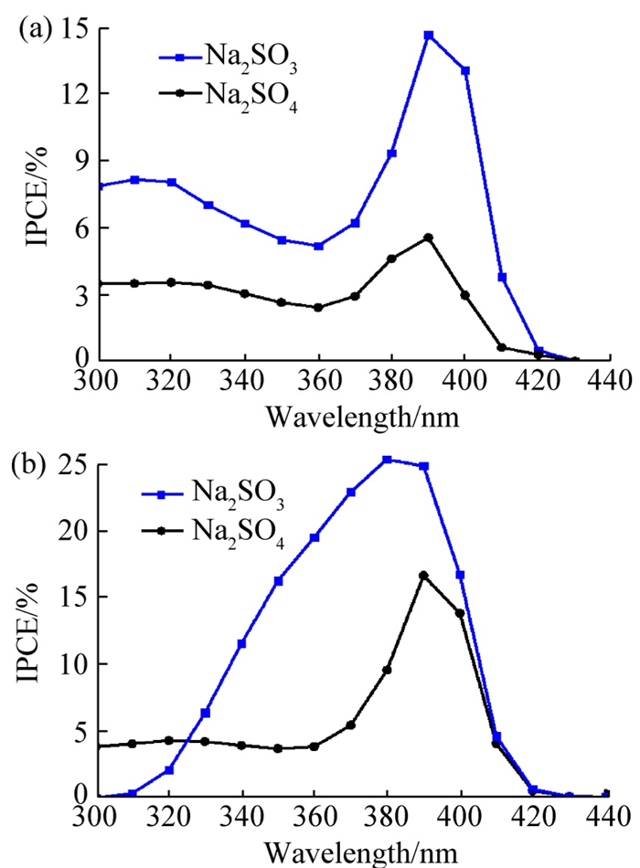 Fig. 5 incident photon-to-current conversion efficiency(IPCE)plots of TiO2 nanowire array electrodes measured in Na2SO3 and Na2SO4 electrolytes(a)0;(b)0.5 V versus Ag/AgCl下载:
全尺寸图片
2.4 MS and EIS characterization
The above experimental results clearly show that the TiO2 nanowire array electrode achieves enhanced PEC performance in Na2SO3 electrolyte compared with that in Na2SO4 electrolyte. As reported in previous work[47], Na2SO3 electrolyte was usually used as a hole scavenger and electron donor in PEC reaction process, possibly resulting in the change of carrier concentration. To understand if the enhanced PEC performance of the TiO2 nanowire array electrode is induced by a carrier concentration change in Na2SO3 electrolyte. MS measurements were measured in both Na2SO3 and Na2SO4 electrolytes under dark and light illumination as shown in figure 6. As shown in figure 6(a), it can be found that the TiO2 nanowire array electrode shows a positive slope in both Na2SO3 and Na2SO4 electrolytes under dark conditions, indicating the inherent n-type characteristics of TiO2 with electrons as the majority carrier. The carrier concentration can be calculated by MS equation[48-49]. As shown in figure 6(b), the calculated ND value of TiO2 nanowire array electrodes in Na2SO3 electrolyte is 1.017 6×1019 cm-3, which is almost one order of magnitude larger than that(6.012×1018 cm-3) in Na2SO4 electrolyte under light illumination. The much larger ND value in Na2SO3 electrolyte results from the effective separation of electrons and holes induced by the consumption of holes with SO3 2- ions. The calculated flat-band potential(Efb)values and donor densities(ND)are presented in table 1.
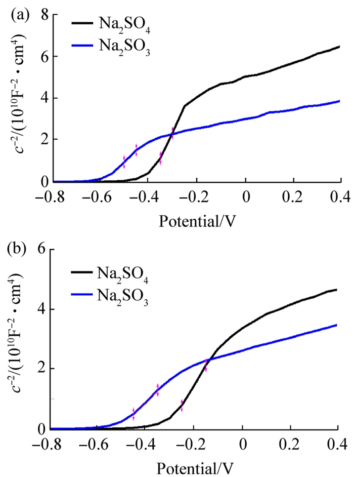 Fig. 6 Mott-Schottky plots of the TiO2 nanowire array electrode in 0.5 mol/L Na2SO3 and 0.5 mol/L Na2SO4 electrolytes(a)dark; (b)1 sun illumination下载:
全尺寸图片
Table 1 the electronic parameters calculated from Mott-Schottky plots
condition electrolyte Efb(V versus Ag/AgCl) ND/1018cm-3 dark Na2SO3 -0.6 7.04 Na2SO4 -0.4 3.30 light Na2SO3 -0.5 10.18 Na2SO4 -0.3 6.01 Note: Efb is flat-band potential; ND is donor density. EIS is a powerful technique to study the charge transfer process of electrodes. To gain further insight into the charge transfer process, the EIS spectra were measured in separate Na2SO3 and Na2SO4 electrolytes under dark and light illumination. The Nyquist plots of TiO2 nanowire array electrodes measured at open circuit potential under dark conditions are shown in figure 7(a). The semicircle located at the high frequency is related to the charge transfer of the semiconductor, and the semicircles at the intermediate and low frequency are associated with the charge transfer and transport at the interface[50-51]. The semicircles associated with charge transfer are too large to be observed directly because the interface charge transfer resistance(Rct)of both TiO2/Na2SO3 and TiO2/Na2SO4 is large. The Rct values for TiO2/Na2SO3 and TiO2/Na2SO4 interfaces are 1.33×10⁴ and 1.23×10⁴ Ω, respectively. Meanwhile, the calculated resistances of solution(Rs)for TiO2 nanowire array electrodes in separate Na2SO3 and Na2SO4 electrolytes are 13.9 and 13.61 Ω, indicating that the electrical circuit scheme is reasonable(inset of figure 7(a)).
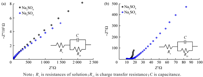 Fig. 7 Nyquist plots of the TiO2 nanowire array electrode in 0.5 mol/L Na2SO3 and 0.5 mol/L Na2SO4 electrolytesNote: Rs is resistances of solution; Rct is charge transfer resistance; C is capacitance.
(a)dark; (b)1 sun illumination下载:
全尺寸图片
The Nyquist plots obtained in both Na2SO3 and Na2SO4 electrolytes at open circuit potential under illumination are shown in figure 7(b). The Rs values for TiO2 nanowire array electrodes in both Na2SO3 and Na2SO4 electrolytes are the same as those in dark conditions. However, the Rct values for TiO2/Na2SO3 and TiO2/Na2SO4 interfaces are much lower than those in dark conditions. Moreover, the Rct value for TiO2/Na2SO3 interface is 515 Ω, which is much lower than that(1 616 Ω)of TiO2/Na2SO4 interfaces. The much lower Rct value for TiO2/Na2SO3 interfaces is ascribed to the effective separation of electrons and holes. Consequently, the separated electrons transfer to the Pt electrode, leading to a much lower Rct and improved PEC performance. The calculated equivalent-circuit fitting parameters are given in table 2.
Table 2 the equivalent-circuit fitting parameterscondition electrolyte Rs/Ω Rct/Ω C/F dark Na2SO3 13.90 1.33×10⁴ 1.71×10⁻⁵ Na2SO4 13.61 1.23×10⁴ 1.04×10⁻⁵ light Na2SO3 13.17 515.10 1.58×10⁻³ Na2SO4 13.23 1 616.00 2.19×10⁻⁴ 2.5 Mechanism for enhanced PEC performance
In a PEC cell, the holes at the interface of electrode and electrolyte are used for water oxidation to O2, and the electrons are transferred to the Pt counter electrode for water reduction to H2. In this study, in the Na2SO4 electrolyte, the photoexcited electrons and holes of TiO2 nanowire array electrodes are easily to be recombined, resulting in low PEC performance. However, in the Na2SO3 electrolyte, SO32- anions can react with holes at the electrode/electrolyte interface to form SO4 2- anions as shown in equations(1-1 and 1-2), thus a competitive oxidation reaction occurs between holes oxidize SO32- anions to form SO42- anions and oxidize water to form O2 as shown in equations(2-1 and 2-2):
$$ \mathrm{SO}_3^{2-}+2 \mathrm{OH}^{-}=\mathrm{SO}_4^{2-}+\mathrm{H}_2 \mathrm{O}+2 \mathrm{e}^{-}, $$ (1-1) $$ E^0=-0.9362 \mathrm{~V} \text { versus NHE, } $$ (1-2) $$ 4 \mathrm{OH}^{-}=2 \mathrm{H}_2 \mathrm{O}+\mathrm{O}_2+4 \mathrm{e}^{-}, $$ (2-1) $$ E^0=0.4009 \mathrm{~V} \text { versus NHE, } $$ (2-2) where E0 denotes the standard electrode potential of each half-reaction, versus NHE indicates the potential is referenced to the normal hydrogen electrode. The above equations show that the redox potential(E0=-0.936 2 V versus NHE)of SO32- anion is much lower than that(E0=0.400 9 V versus NHE)of OH- anion, so the oxidation of SO32- anion by holes is thermodynamically more favorable than the oxidation of OH- anion by holes. A large number of SO3 2- anions in electrolyte can consume a lot of photogenerated holes at the electrode/electrolyte interface, resulting in the efficient separation of electrons and holes. The separated electrons transfer to Pt electrode via an external circuit to reduce water, leading to enhanced photocurrent and PEC performance of TiO2 nanowire array electrodes in Na2SO3 electrolyte. Figure 8 is a schematic for illustrating the transfer process of electrons and holes for TiO2 nanowire array electrodes in Na2SO3 electrolyte.
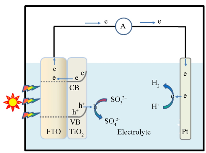 Fig. 8 schematic illustration for the charge transfer and separation of TiO2 nanowire array electrodes in Na2SO3 electrolyteNote: FTO represents fluorine-doped tin oxide; CB and VB represent conduction band and valence band, respectively.下载:
全尺寸图片
3. Conclusions
In conclusion, the effects of Na2SO4 and Na2SO3 electrolytes on the PEC performance of TiO2 nanowire array electrodes were studied. The TiO2 nanowire array electrode shows remarkable enhancement for PEC performance in Na2SO3 electrolyte, compared with that in Na2SO4 electrolyte. The mechanism for enhanced PEC performance was discussed in detail. The Mott-Schottky and electrochemical impedance spectroscopy measurements experimentally show that the efficient separation of electrons and holes induced by the consumption of holes with SO32- is responsible for the enhanced PEC performance of TiO2 nanowire array electrodes in Na2SO3 electrolyte. The findings achieved in this study offer an effective and promising strategy for improving the PEC performance of electrode through optimization of electrolyte.
© The editorial department of Journal of Capital Normal University (Natural Science Edition) 2025.This is an open access article under the CC BY-NC-ND 4.0 license (https://creativecommons.org/licenses/by-nc-nd/4.0/). -
Fig. 1 X-ray diffraction(XRD)patterns of TiO2 nanowire arrays (NWAs)(black line) and the fluorine-doped tin oxide(FTO)substrate(red line)
下载:
全尺寸图片
Fig. 2 scanning electron microscopy(SEM)images with different magnification of TiO2 NWAs grown the FTO substrate
(a)low; (b, c)medium; (d)high
下载:
全尺寸图片
Fig. 3 optical property of TiO2 NWAs
(a)UV-vis diffuse reflectance spectrum; (b)(F(R)hν)1/2 versus hν plot of TiO2 NWAs
下载:
全尺寸图片
Fig. 4 I-t curves measured in both Na2SO4 and Na2SO3 electrolytes
(a)0;(b)0.5 V versus Ag/AgCl; (c)linear sweep voltammograms(LSV)curves
下载:
全尺寸图片
Fig. 5 incident photon-to-current conversion efficiency(IPCE)plots of TiO2 nanowire array electrodes measured in Na2SO3 and Na2SO4 electrolytes
(a)0;(b)0.5 V versus Ag/AgCl
下载:
全尺寸图片
Fig. 6 Mott-Schottky plots of the TiO2 nanowire array electrode in 0.5 mol/L Na2SO3 and 0.5 mol/L Na2SO4 electrolytes
(a)dark; (b)1 sun illumination
下载:
全尺寸图片
Fig. 7 Nyquist plots of the TiO2 nanowire array electrode in 0.5 mol/L Na2SO3 and 0.5 mol/L Na2SO4 electrolytes
Note: Rs is resistances of solution; Rct is charge transfer resistance; C is capacitance.
(a)dark; (b)1 sun illumination下载:
全尺寸图片
Fig. 8 schematic illustration for the charge transfer and separation of TiO2 nanowire array electrodes in Na2SO3 electrolyte
Note: FTO represents fluorine-doped tin oxide; CB and VB represent conduction band and valence band, respectively.
下载:
全尺寸图片
Table 1 the electronic parameters calculated from Mott-Schottky plots
condition electrolyte Efb(V versus Ag/AgCl) ND/1018cm-3 dark Na2SO3 -0.6 7.04 Na2SO4 -0.4 3.30 light Na2SO3 -0.5 10.18 Na2SO4 -0.3 6.01 Note: Efb is flat-band potential; ND is donor density. Table 2 the equivalent-circuit fitting parameters
condition electrolyte Rs/Ω Rct/Ω C/F dark Na2SO3 13.90 1.33×10⁴ 1.71×10⁻⁵ Na2SO4 13.61 1.23×10⁴ 1.04×10⁻⁵ light Na2SO3 13.17 515.10 1.58×10⁻³ Na2SO4 13.23 1 616.00 2.19×10⁻⁴ -
[1] Fujishima A, Honda K. Electrochemical photolysis of water at a semiconductor electrode[J]. Nature, 1972, 238(5358): 37-38. DOI: 10.1038/238037a0. [2] Moniz S J A, Shevlin S A, Martin D J, et al. Visible-light driven heterojunction photocatalysts for water splitting: a critical review[J]. Energy & Environmental Science, 2015, 8(3): 731-759. DOI: 10.1039/C4EE03271C. [3] Feng T X, Yam F K. A review of TiO2 nanostructured materials for hydrogen generation through photocatalytic and photoelectrochemical water splitting[J]. Physica B: Condensed Matter, 2025, 714: 417466. DOI: 10.1016/j.physb.2025.417466. [4] Guo M Q, Chen R, Wang D W, et al. Optimized photoelectrochemical water splitting via morphology-engineered TiO2 nanostructured photoelectrodes: a comparative study[J]. Materials Letters, 2025, 400: 139124. DOI: 10.1016/j.matlet.2025.139124. [5] Hill J C, Choi K S. Effect of electrolytes on the selectivity and stability of n-type WO3 photoelectrodes for use in solar water oxidation[J]. The Journal of Physical Chemistry C, 2012, 116(14): 7612-7620. DOI: 10.1021/jp209909b. [6] Mi Q X, Coridan R H, Brunschwig B S, et al. Photoelectrochemical oxidation of anions by WO3 in aqueous and nonaqueous electrolytes[J]. Energy & Environmental Science, 2013, 6(9): 2646-2653. DOI: 10.1039/C3EE40712H. [7] Mi Q X, Zhanaidarova A, Brunschwig B S, et al. A quantitative assessment of the competition between water and anion oxidation at WO3 photoanodes in acidic aqueous electrolytes [J]. Energy & Environmental Science, 2012, 5 (2): 5694-5700. DOI: 10.1039/C2EE02929D. [8] Zhang X, Liu Y, Kang Z H. 3D branched ZnO nanowire arrays decorated with plasmonic Au nanoparticles for high-performance photoelectrochemical water splitting [J]. ACS Applied Materials & Interfaces, 2014, 6(6): 4480-4489. DOI: 10.1021/am500234v. [9] Yang X Y, Wolcott A, Wang G M, et al. Nitrogen-doped ZnO nanowire arrays for photoelectrochemical water splitting[J]. Nano letters, 2009, 9(6): 2331-2336. DOI: 10.1021/nl900772q. [10] Ding C M, Shi J Y, Wang D G, et al. Visible light driven overall water splitting using cocatalyst/BiVO4 photoanode with minimized bias[J]. Physical Chemistry Chemical Physics, 2013, 15(13): 4589-4595. DOI: 10.1039/C3CP50295C. [11] McDonald K J, Choi K S. A new electrochemical synthesis route for a BiOI electrode and its conversion to a highly efficient porous BiVO4 photoanode for solar water oxidation[J]. Energy & Environmental Science, 2012, 5(9): 8553-8557. DOI: 10.1039/C2EE22608A. [12] Park Y, Kang D, Choi K S. Marked enhancement in electron-hole separation achieved in the low bias region using electrochemically prepared Mo-doped BiVO4 photoanodes[J]. Physical Chemistry Chemical Physics, 2014, 16(3): 1238-1246. DOI: 10.1039/c3cp53649a. [13] Seabold J A, Choi K S. Efficient and stable photo-oxidation of water by a bismuth vanadate photoanode coupled with an iron oxyhydroxide oxygen evolution catalyst[J]. Journal of the American Chemical Society, 2012, 134(4): 2186-2192. DOI: 10.1021/ja209001d. [14] Huang S M, Liu X Y, Jiang M, et al. Double plasmonic effect and step-like charge transport channel synergistically enhance bulk and surface charge separation efficiency of Au/Cu2O-modified TiO2 photoanode for efficient photoelectrochemical water splitting[J]. Fuel, 2025, 385: 134179. DOI: 10.1016/j.fuel.2024.134179. [15] Shang X Y, Zhang D Y, Li Z W, et al. Photoelectrochemical enhancement for TiO2-based photoanodes: In-situ electrochemical analysis, modification strategies and mechanism studies[J]. Electrochimica Acta, 2024, 502: 144859. DOI: 10.1016/j.electacta.2024.144859. [16] Alotaibi A M, Alzahrani H M, Alosaimi S M, et al. Photoelectrochemical water splitting using TiO2/α-Fe2O3 heterojunction films produced by chemical vapour deposition[J]. RSC Advances, 2025, 15(38): 31931-31945. DOI: 10.1039/D5RA05064B. [17] Guo M Y, Yao S K, Zhang W J, et al. Cobalt-doped rutile/anatase TiO2 photoanode with oriented energy band offset for photoelectrochemical water splitting[J]. Applied Surface Science, 2025, 700: 163159. DOI: 10.1016/j.apsusc.2025.163159. [18] Chen S R, Peng Y, Li C L, et al. The co-decorated TiO2 nanorod array photoanodes by CdS/CdSe to promote photoelectrochemical water splitting[J]. International Journal of Hydrogen Energy, 2021, 46(63): 32055-32068. DOI: 10.1016/j.ijhydene.2021.06.217. [19] Ghoti A N, Patil A B, Pardeshi S K. Li sensitized CdS/TiO2 nanocomposite photoanode for solar water splitting, hydrogen generation and photoelectrochemical (PEC) performance[J]. International Journal of Hydrogen Energy, 2024, 51: 1586-1597. DOI: 10.1016/j.ijhydene.2023.08.025. [20] Tu J L, Li J W, Pan Z F, et al. Nitrogen-doped CdS/TiO2 nanorods heterojunction photoanode for efficient and stable photoelectrochemical water splitting[J]. Journal of Power Sources, 2025, 628: 235883. DOI: 10.1016/j.jpowsour.2024.235883. [21] Singh S V, Gupta U, Biring S, et al. In-situ grown nanoscale p-n heterojuction of Cu2S-TiO2 thin film for efficient photoelectrocatalytic H2 evolution[J]. Surfaces and Interfaces, 2022, 28: 101660. DOI: 10.1016/j.surfin.2021.101660. [22] Wang L, Yu H, Wang Y X, et al. Electrodeposition of ptype Cu2O on n-type TiO2 nanosheet arrays for enhanced photoelectrochemical water splitting[J]. Electrochemistry Communications, 2025, 178: 108009. DOI: 10.1016/j.elecom.2025.108009. [23] Pour-Ali S, Tavangar R, Namdar-Asl H, et al. Enhanced photoelectrochemical water splitting via hydrogenated TiO2 nanotubes modified with Cu/CuO species[J]. Journal of Photochemistry and Photobiology A, 2024, 452: 115586. DOI: 10.1016/j.jphotochem.2024.115586. [24] Tang X H, Li D Y. Sulfur-doped highly ordered TiO2 nanotubular arrays with visible light response[J]. The Journal of Physical Chemistry C, 2008, 112(14): 5405-5409. DOI: 10.1021/jp710468a. [25] Xu J J, Ao Y H, Chen M D, et al. Photoelectrochemical property and photocatalytic activity of N-doped TiO2 nanotube arrays[J]. Applied Surface Science, 2010, 256 (13): 4397-4401. DOI: 10.1016/j.apsusc.2010.02.037. [26] Miseki Y, Kusama H, Sugihara H, et al. Significant effects of anion in aqueous reactant solution on photocatalytic O2 evolution and Fe (Ⅲ) reduction[J]. Chemistry Letters, 2010, 39(8): 846-847. DOI: 10.1246/cl.2010.846. [27] Ding C M, Zhou X, Shi J Y, et al. Abnormal effects of cations (Li+, Na+, and K+) on photoelectrochemical and electrocatalytic water splitting [J]. The Journal of Physical Chemistry B, 2015, 119(8): 3560-3566. DOI: 10.1021/acs.jpcb.5b00713. [28] Zhao W R, Ai Z Y, Dai J S, et al. Enhanced photocatalytic activity for H2 evolution under irradiation of UV-vis light by Au-modified nitrogen-doped TiO2 [J]. PLoS One, 2014, 9(8): e103671. DOI: 10.1371/journal.pone.0103671. [29] Wang Q Y, Li S, Qiao J L, et al. CdS-CdSe (CdTe) core-shell quantum dots sensitized TiO2 nanotube array solar cells[J]. Solar Energy Materials and Solar Cells, 2015, 132: 650-654. DOI: 10.1016/j.solmat.2014.10.014. [30] Tan Y, Zhang S H, Shi R X, et al. Visible light active Ce/Ce2O/CeO2/TiO2 nanotube arrays for efficient hydrogen production by photoelectrochemical water splitting[J]. International Journal of Hydrogen Energy, 2016, 41 (12): 5437-5444. DOI: 10.1016/j.ijhydene.2016.01.154. [31] Wang Q, Zhu N X, Liu E Q, et al. Highly enhanced photoelectrocatalytic properties by α-Fe2O3 modified NFTiO2 pyramids with dominant (101) facets [J]. Electrochimica Acta, 2016, 216(20): 266-275. DOI: 10.1016/j.electacta.2016.09.025. [32] Li H X, Dong W, Xi J H, et al. Hydropowered photoelectrochemical water splitting solar cell for hydrogen production [J]. Journal of Alloys and Compounds, 2017, 691: 750-754. DOI: 10.1016/j.jallcom.2016.08.290. [33] Liu C J, Yang Y H, Li W Z, et al. A novel Bi2S3 nanowire @ TiO2 nanorod heterogeneous nanostructure for photoelectrochemical hydrogen generation [J]. Chemical Engineering Journal, 2016, 302(8): 717-724. DOI: 10.1016/j.cej.2016.05.126. [34] Kim T W, Choi K S. Nanoporous BiVO4 photoanodes with dual-layer oxygen evolution catalysts for solar water splitting[J]. Science, 2014, 343(6174): 990-994. DOI: 10.1126/science.1246913. [35] Yang S M, Huang C H, Zhai J, et al. High photostability and quantum yield of nanoporous TiO2 thin film electrodes co-sensitized with capped sulfides[J]. Journal of Materials Chemistry, 2002, 12(5): 1459-1464. DOI: 10.1039/b105796k. [36] Liu B, Aydil E S. Growth of oriented single-crystalline rutile TiO2 nanorods on transparent conducting substrates for dye-sensitized solar cells [J]. Journal of the American Chemical Society, 2009, 131(11): 3985-3990. DOI: 10.1021/ja8078972. [37] Ghaffari M, Cosar M B, Yavuz H I, et al. Effect of Au nano-particles on TiO2 nanorod electrode in dye-sensitized solar cells[J]. Electrochimica Acta, 2012, 76: 446-452. DOI: 10.1016/j.electacta.2012.05.058. [38] López R, Gómez R. Band-gap energy estimation from diffuse reflectance measurements on sol-gel and commercial TiO2: a comparative study[J]. Journal of Sol-Gel Science and Technology, 2012, 61(1): 1-7. DOI: 10.1007/s10971-011-2582-9. [39] Murphy A B. Band-gap determination from diffuse reflectance measurements of semiconductor films, and application to photoelectrochemical water-splitting[J]. Solar Energy Materials and Solar Cells, 2007, 91(14): 1326-1337. DOI: 10.1016/j.solmat.2007.05.005. [40] Kong M, Li Y Z, Chen X, et al. Tuning the relative concentration ratio of bulk defects to surface defects in TiO2 nanocrystals leads to high photocatalytic efficiency [J]. Journal of the American Chemical Society, 2011, 133 (41): 16414-16417. DOI: 10.1021/ja207826q. [41] He Y M, Cai J, Li T T, et al. Efficient degradation of RhB over GdVO4/g-C3N4 composites under visible-light irradiation[J]. Chemical Engineering Journal, 2013, 215: 721-730. DOI: 10.1016/j.cej.2012.11.074. [42] Dotan H, Sivula K, Grätzel M, et al. Probing the photoelectrochemical properties of hematite (α-Fe2O3) electrodes using hydrogen peroxide as a hole scavenger [J]. Energy & Environmental Science, 2011, 4 (3): 958-964. DOI: 10.1039/c0ee00570c. [43] Horowitz G. Capacitance-voltage measurements and flat-band potential determination on Zr-doped α-Fe2O3 single-crystal electrodes [J]. Journal of Electroanalytical Chemistry and Interfacial Electrochemistry, 1983, 159 (2): 421-436. DOI: 10.1016/S0022-0728(83)80638-X. [44] Dare-Edwards M P, Goodenough J B, Hamnett A, et al. Electrochemistry and photoelectrochemistry of iron (Ⅲ) oxide[J]. Journal of the Chemical Society, Faraday Transactions, 1983, 79(9): 2027-2041. DOI: 10.1039/f19837902027. [45] Hagfeldt A, Lindström H, Södergren S S, et al. Photoelectrochemical studies of colloidal TiO2 films: the effect of oxygen studied by photocurrent transients[J]. Journal of Electroanalytical Chemistry, 1995, 381 (1/2): 39-46. DOI: 10.1016/0022-0728(94)03622-A. [46] Dinh H, Chen Z B, Miller E. Photoelectrochemical water splitting[M]. New York: Springer, 2013. [47] Tsuji I, Kato H, Kobayashi H, et al. Photocatalytic H2 evolution reaction from aqueous solutions over band structure-controlled (AgIn)xZn2(1−x)S2 solid solution photocatalysts with visible-light response and their surface nanostructures[J]. Journal of the American Chemical Society, 2004, 126(41): 13406-13413. DOI: 10.1021/ja048296m. [48] Degryse R, Gomes W P, Cardon F, et al. On the interpretation of Mott-Schottky plots determined at semiconductor/electrolyte systems[J]. Journal of the Electrochemical Society, 1975, 122(5): 711-712. DOI: 10.1149/1.2134298. [49] Salvador P. Hole diffusion length in n-TiO2 single crystals and sintered electrodes: photoelectrochemical determination and comparative analysis[J]. Journal of Applied Physics, 1984, 55 (8): 2977-2985. DOI: 10.1063/1.333358. [50] Zhang J, Yu J G, Jaroniec M, et al. Noble metal-free reduced graphene oxide-ZnxCd1−xS nanocomposite with enhanced solar photocatalytic H2-production performance [J]. Nano Letters, 2012, 12(9): 4584-4589. DOI: 10.1016/j.apcatb.2018.05.025. [51] Choi M, Lee J H, Jang Y J, et al. Hydrogen-doped brookite TiO2 nanobullets array as a novel photoanode for efficient solar water splitting[J]. Scientific Reports, 2016, 6: 36099. DOI: 10.1038/srep36099.
